Embedded systems are ubiquitous in our modern world, powering everything from smart home devices to automotive control systems. At the heart of many of these systems lies the C programming language, renowned for its efficiency and low-level control. In this comprehensive guide, we'll delve into the fascinating world of embedded programming with C, exploring its fundamental concepts and practical applications.
Understanding Embedded Systems
🔧 An embedded system is a computer system designed for specific control functions within a larger system, often with real-time computing constraints. Unlike general-purpose computers, embedded systems are dedicated to specific tasks and are optimized for reliability, performance, and energy efficiency.
Embedded systems typically consist of:
- Microcontroller or microprocessor
- Memory (RAM and ROM)
- Input/Output interfaces
- Specialized hardware components
C is the language of choice for many embedded systems due to its:
- Efficiency and low overhead
- Direct hardware manipulation capabilities
- Portability across different architectures
- Rich ecosystem of tools and libraries
Setting Up the Development Environment
Before we dive into coding, let's set up a basic development environment for embedded C programming. While the exact setup can vary depending on your target hardware, a typical environment includes:
- A C compiler (e.g., GCC for ARM)
- An Integrated Development Environment (IDE) like Eclipse or Keil µVision
- A debugger (e.g., GDB)
- A hardware programmer or simulator
For this tutorial, we'll use a simulated environment to focus on the programming concepts.
Hello, Embedded World!
Let's start with the classic "Hello, World!" program, adapted for an embedded system:
#include <stdio.h>

#define LED_PORT (*((volatile unsigned char *)0x20))
#define LED_PIN 5

void delay(int count) {
    volatile int i;
    for (i = 0; i < count; i++);
}

int main() {
    // Configure LED pin as output
    LED_PORT |= (1 << LED_PIN);

    while (1) {
        // Toggle LED
        LED_PORT ^= (1 << LED_PIN);
        delay(100000);  // Delay for visibility
    }

    return 0;
}
Let's break down this program:
-
We define
LED_PORTas a pointer to a volatile unsigned char at memory address 0x20. This is typically where a microcontroller's GPIO (General Purpose Input/Output) register would be located. -
LED_PINis defined as 5, representing the pin number we're using for our LED. -
The
delayfunction is a simple busy-wait loop. In real embedded systems, we'd use hardware timers for more accurate timing. -
In
main(), we first configure the LED pin as an output by setting its bit in the port register. -
The infinite
whileloop toggles the LED state and introduces a delay for visibility.
This program demonstrates several key concepts in embedded C programming:
- Direct hardware register manipulation
- Bit-level operations
- Infinite loops for continuous operation
- Simple timing mechanisms
Memory Management in Embedded Systems
Memory management is crucial in embedded systems due to limited resources. Let's explore different memory types and their usage:
#include <stdio.h>

// Global variables (stored in .data or .bss sections)
int globalVar = 10;
static int staticGlobalVar;

// Function using stack memory
void stackFunction(int parameter) {
    int localVar = 5;
    printf("Local variable: %d\n", localVar);
    printf("Parameter: %d\n", parameter);
}

// Function demonstrating static local variable
void staticLocalFunction() {
    static int count = 0;
    count++;
    printf("This function has been called %d times\n", count);
}

int main() {
    // Dynamic memory allocation (heap)
    int *heapVar = (int *)malloc(sizeof(int));
    *heapVar = 20;

    printf("Global variable: %d\n", globalVar);
    printf("Static global variable: %d\n", staticGlobalVar);
    printf("Heap variable: %d\n", *heapVar);

    stackFunction(15);
    staticLocalFunction();
    staticLocalFunction();

    // Don't forget to free heap memory
    free(heapVar);

    return 0;
}
This program demonstrates different types of memory usage in C:
- Global Variables: Stored in the .data section (if initialized) or .bss section (if uninitialized) of memory.
- Stack Memory: Used for local variables and function parameters.
- Heap Memory: Used for dynamic memory allocation.
- Static Variables: Retain their values between function calls.
In embedded systems, we often avoid dynamic memory allocation due to potential fragmentation and unpredictable behavior. Instead, we rely more on static allocation and careful management of stack usage.
Interrupt Handling
Interrupts are crucial in embedded systems for handling asynchronous events. Here's a simple example of interrupt handling:
#include <stdio.h>
#include <avr/io.h>
#include <avr/interrupt.h>

volatile uint8_t button_pressed = 0;

// Interrupt Service Routine for INT0
ISR(INT0_vect) {
    button_pressed = 1;
}

void setup() {
    // Configure INT0 (PD2) as input with pull-up
    DDRD &= ~(1 << PD2);
    PORTD |= (1 << PD2);

    // Configure INT0 to trigger on falling edge
    EICRA |= (1 << ISC01);
    EICRA &= ~(1 << ISC00);

    // Enable INT0
    EIMSK |= (1 << INT0);

    // Enable global interrupts
    sei();
}

int main() {
    setup();

    while (1) {
        if (button_pressed) {
            printf("Button pressed!\n");
            button_pressed = 0;
        }
    }

    return 0;
}
This program sets up an interrupt on the INT0 pin (typically connected to a button):
- We define a volatile flag
button_pressedto communicate between the ISR and the main loop. - The
ISR(INT0_vect)function is the Interrupt Service Routine that runs when INT0 is triggered. - In
setup(), we configure INT0 as an input with a pull-up resistor, set it to trigger on a falling edge, and enable the interrupt. - The main loop checks the
button_pressedflag and responds accordingly.
Key points about interrupt handling in embedded C:
- Use the
volatilekeyword for variables shared between ISRs and the main program. - Keep ISRs as short as possible to maintain system responsiveness.
- Be aware of shared resource issues when using interrupts.
Bit Manipulation Techniques
Efficient bit manipulation is essential in embedded programming for tasks like configuring registers or optimizing memory usage. Let's explore some common techniques:
#include <stdio.h>
#include <stdint.h>

// Function to set a specific bit
uint8_t setBit(uint8_t byte, uint8_t position) {
    return byte | (1 << position);
}

// Function to clear a specific bit
uint8_t clearBit(uint8_t byte, uint8_t position) {
    return byte & ~(1 << position);
}

// Function to toggle a specific bit
uint8_t toggleBit(uint8_t byte, uint8_t position) {
    return byte ^ (1 << position);
}

// Function to check if a specific bit is set
uint8_t checkBit(uint8_t byte, uint8_t position) {
    return (byte & (1 << position)) != 0;
}

int main() {
    uint8_t data = 0b10101010;  // Initial data

    printf("Initial data: 0b%08b\n", data);

    data = setBit(data, 2);
    printf("After setting bit 2: 0b%08b\n", data);

    data = clearBit(data, 5);
    printf("After clearing bit 5: 0b%08b\n", data);

    data = toggleBit(data, 7);
    printf("After toggling bit 7: 0b%08b\n", data);

    printf("Is bit 3 set? %s\n", checkBit(data, 3) ? "Yes" : "No");

    return 0;
}
This program demonstrates four common bit manipulation techniques:
- Setting a bit: Using the OR operation with a bitmask.
- Clearing a bit: Using the AND operation with an inverted bitmask.
- Toggling a bit: Using the XOR operation.
- Checking a bit: Using the AND operation and comparing the result.
Output:
Initial data: 0b10101010
After setting bit 2: 0b10101110
After clearing bit 5: 0b10001110
After toggling bit 7: 0b00001110
Is bit 3 set? No
These techniques are crucial for efficiently manipulating hardware registers and optimizing memory usage in embedded systems.
Timers and PWM
Timers are essential components in embedded systems for tasks like generating precise delays, measuring time intervals, or creating PWM (Pulse Width Modulation) signals. Let's look at a simple example of using a timer to generate a PWM signal:
#include <avr/io.h>
#include <avr/interrupt.h>

#define F_CPU 16000000UL  // CPU frequency
#define PWM_FREQUENCY 1000  // Desired PWM frequency

void initPWM() {
    // Set up Timer1 in Fast PWM mode
    TCCR1A |= (1 << COM1A1) | (1 << WGM11);
    TCCR1B |= (1 << WGM13) | (1 << WGM12) | (1 << CS10);

    // Set PWM period
    ICR1 = F_CPU / PWM_FREQUENCY - 1;

    // Set initial duty cycle to 50%
    OCR1A = ICR1 / 2;

    // Configure OC1A (PB1) as output
    DDRB |= (1 << PB1);
}

void setPWMDutyCycle(uint8_t duty) {
    OCR1A = (uint16_t)((uint32_t)ICR1 * duty / 100);
}

int main() {
    initPWM();

    while (1) {
        // Example: Gradually increase duty cycle from 0% to 100%
        for (uint8_t duty = 0; duty <= 100; duty++) {
            setPWMDutyCycle(duty);
            _delay_ms(50);  // Delay for visibility
        }
    }

    return 0;
}
This program sets up Timer1 on an AVR microcontroller to generate a PWM signal:
initPWM()configures Timer1 in Fast PWM mode with a frequency of 1 kHz.setPWMDutyCycle()allows changing the duty cycle of the PWM signal.- The main loop demonstrates gradually increasing the duty cycle from 0% to 100%.
Key points about using timers and PWM in embedded systems:
- Timers can be used for precise timing, event counting, and signal generation.
- PWM is useful for controlling motor speed, LED brightness, and other analog-like outputs using digital signals.
- Proper configuration of timer registers is crucial for achieving the desired behavior.
Communication Protocols
Embedded systems often need to communicate with other devices or sensors. Let's look at an example of implementing a simple UART (Universal Asynchronous Receiver/Transmitter) communication:
#include <avr/io.h>
#include <util/delay.h>

#define F_CPU 16000000UL  // CPU frequency
#define BAUD 9600  // Desired baud rate
#define UBRR_VALUE ((F_CPU/16/BAUD) - 1)

void UART_init() {
    // Set baud rate
    UBRR0H = (uint8_t)(UBRR_VALUE >> 8);
    UBRR0L = (uint8_t)UBRR_VALUE;

    // Enable receiver and transmitter
    UCSR0B = (1 << RXEN0) | (1 << TXEN0);

    // Set frame format: 8 data bits, 1 stop bit, no parity
    UCSR0C = (1 << UCSZ01) | (1 << UCSZ00);
}

void UART_transmit(uint8_t data) {
    // Wait for empty transmit buffer
    while (!(UCSR0A & (1 << UDRE0)));

    // Put data into buffer, sends the data
    UDR0 = data;
}

uint8_t UART_receive() {
    // Wait for data to be received
    while (!(UCSR0A & (1 << RXC0)));

    // Get and return received data from buffer
    return UDR0;
}

void UART_print_string(const char* str) {
    while (*str) {
        UART_transmit(*str++);
    }
}

int main() {
    UART_init();

    while (1) {
        UART_print_string("Hello, Embedded World!\r\n");
        _delay_ms(1000);  // Delay for 1 second

        // Echo received characters
        if (UCSR0A & (1 << RXC0)) {
            uint8_t received = UART_receive();
            UART_transmit(received);
        }
    }

    return 0;
}
This program implements basic UART communication:
UART_init()sets up the UART with a baud rate of 9600, 8 data bits, 1 stop bit, and no parity.UART_transmit()sends a single byte.UART_receive()receives a single byte.UART_print_string()sends a null-terminated string.- The main loop sends a greeting message every second and echoes any received characters.
Other common communication protocols in embedded systems include:
- I2C (Inter-Integrated Circuit)
- SPI (Serial Peripheral Interface)
- CAN (Controller Area Network)
Each protocol has its advantages and is suited for different applications.
Conclusion
Embedded C programming is a vast and exciting field that combines the power of C with the intricacies of hardware control. We've covered several fundamental concepts:
- Basic embedded program structure
- Memory management considerations
- Interrupt handling
- Bit manipulation techniques
- Timer and PWM usage
- Communication protocols
These form the foundation of embedded systems development, but there's much more to explore, including:
- Real-time operating systems (RTOS)
- Power management techniques
- Debugging and testing strategies
- Security considerations
As you continue your journey in embedded systems programming, remember that practice and hands-on experience are key. Experiment with different microcontrollers, sensors, and actuators to build your skills and understanding.
Embedded systems are at the heart of the Internet of Things (IoT) revolution, making our world smarter and more connected. By mastering embedded C programming, you're equipping yourself with the skills to shape this exciting future.
Happy coding, and may your embedded adventures be bug-free and endlessly rewarding! 🚀🔧💻
Related Posts
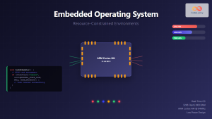
Embedded Operating System: Complete Guide to Resource-Constrained Environments
Embedded operating systems form the backbone of countless devices we interact with daily, from smart home appliances to automotive control...

C Real-Life Examples: Practical Applications of C
C, the venerable programming language, continues to be a powerhouse in the world of software development. Its efficiency, portability, and...

C Environment Setup: Installation and Configuration
Welcome to the world of C programming! 🖥️ Whether you're a beginner taking your first steps into coding or an...

C Standard Library: <stdlib.h> Functions
The C Standard Library is a collection of header files that provide a wide array of functions, macros, and type...

Process in Operating System: Complete Guide to Definition, States and Lifecycle
What is a Process in Operating System? A process is a program in execution that consists of the program code...
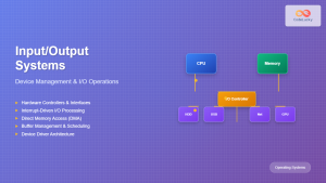
Input Output Systems: Complete Guide to Device Management and I/O Operations
Input/Output (I/O) systems form the critical bridge between a computer's internal processing capabilities and the external world. These systems manage...

C Memory Management: Advanced Techniques and Best Practices
Memory management is a critical aspect of C programming that can make or break your application's performance and reliability. In...

C Standard Library: <stdio.h> Functions
The C programming language is renowned for its efficiency and power, and much of this comes from its extensive standard...

Dynamic Memory Allocation: malloc, calloc and free Functions in C Programming
What is Dynamic Memory Allocation? Dynamic memory allocation is a fundamental concept in operating systems and programming that allows programs...
C Syntax: Basic Rules and Structure
C is a powerful and versatile programming language that has stood the test of time. Its influence can be seen...

C Functions: Defining and Calling Functions
Functions are the building blocks of C programming, allowing you to organize your code into reusable, manageable pieces. In this...

C Thread Programming: Introduction to Multithreading
In the world of modern computing, efficiency is key. As processors become more powerful and capable of handling multiple tasks...